Driving an RC car is fun. But I think it’s much more fun to break things apart and see what else can be done with it. I decided to buy a cheap remote controlled car with a goal of controlling it with a keyboard and an Arduino. If you have any experience in programming but have not touched electronics before, you’re still able to follow along. It’s not difficult at all.
The way I’m going to control an RC car is to open up its controller and plug an Arduino to it. This way I’m able to programmatically control the switches.
Things you’re going to need:
- A cheap RC car (obviously)
- An Arduino board (I’m using the Arduino Uno)
- Soldering equipment
- Multimeter
- Some electronic components
- 4 octocouplers
- 4 220k ohm resistors
- a breadboard
- jumper wires
What kind of a car do I need?
I got the cheapest one I could find. The only requirement is that it should have on/off type controls. Meaning that if you press a switch, the car either drives forwards or does nothing.
Open up the RC controller
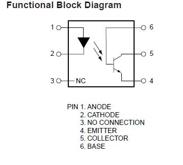
The next step is to figure out how the RC controller works. It’s relatively simple. When you open the controller, you can see 4 push button switches on the circuit board. The idea is that instead of a human pushing a switch you can simulate a switch being pressed with an Arduino. For that I’m going to use optocouplers to make a connection from the switch to ground. Optocouplers are integrated circuits which allow you to control devices that are on a different circuit. Inside an optocoupler is an LED and a light detector. When the LED is turned on the light detector closes a switch. This allows you to connect an Arduino to a different circuit and have them be electrically separated.

Looking at the controller circuit, you need to determine which parts of the circuit are closed by the switches on the board. Take out a multimeter, put it into diode mode and try to connect one end of the switch to ground. If you have the RC car turned on you should see a response from the car.
Soldering wires
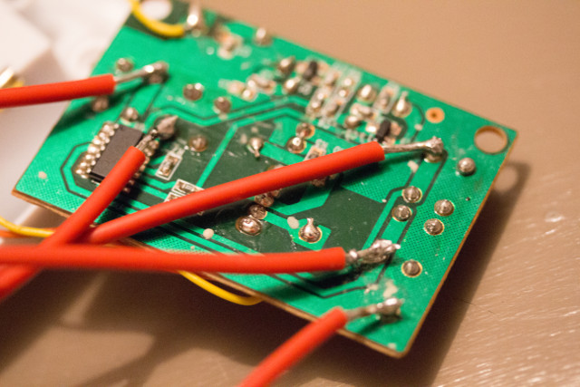
After doing some tests with a multimeter, you should have a pretty good understanding of the layout. The next step is to solder some wires to the circuit. I used 5 wires, 4 for each switch and 1 for ground. If you connect either of the four wires to ground, the corresponding switch should be closed and you should see a response from the car. Later I can plug the soldered wires to a breadboard and connect them with optocouplers.
The following is the result after I had finished soldering.

The bottom right wire is ground and the other four are connected to switches. On this picture you can see a chip on the circuit board. This is the RX2/TX2 chip that’s found on most cheap RC cars. It uses 2 channels to control the car but apparently it has a third unused channel. If you’re up for it you can build additional functionality to your car.
Building the circuit
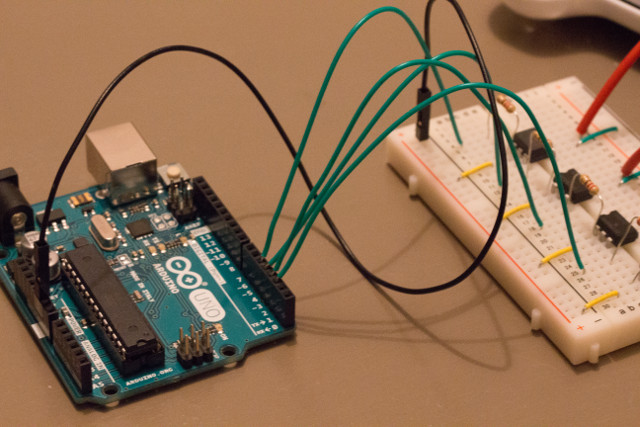
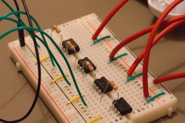
When the soldering is done, the next step is to connect the wires to a breadboard and add some other electronic components there as well. I don’t have a background in electrical engineering. Therefore I cannot draw you a schematic with the correct electrical symbols. But I can take pictures of the end result.


Arduino pins 2, 3, 4 and 5 are connected to optocouplers through a 220k ohm resistor. In the picture, pin 2 and 3 control the backwards and forwards switch respectively. Pin number 4 and 5 are responsible for turning left or right. So for example when pin 2 outputs 5 volts, the optocoupler closes its switch which in turn closes the switch in the RC car controller’s circuit and the car should start to drive backwards.
Putting it into code
My laptop is going to communicate with the Arduino using a serial connection over a USB cable. The goal is to send as little data as possible. Therefore a command is sent only when a key is pressed or released. There’s four different directions the car could drive and two possible states (pressed and released), that means eight unique commands in total.
On my laptop I run a Python script which starts to detect key presses and sends commands over a serial connection to an Arduino. Commands are received and processed by the Arduino. It stores whether a key is currently pressed or released and based on that sets the appropriate pins high or low.
To see the source code, head over to this Github repository.
Hack your own RC car!
If you have not done anything like this before, then this is a good place to start. It is not difficult at all and it’s satisfying to see the car move when you press a key on your keyboard. Make use of the source code provided. Modify it and make your own cool remote controlled car.

