
Some time ago I bought my first Arduino. I have several years of experience as a software developer but my knowledge of electronics is pretty minimal. For my first project I decided to control a cheap RC car with an Arduino board. This was done by connecting the board to the car’s controller and sending commands from my laptop to the Arduino over a serial connection. Basically I made the original controller programmable and the car would still receive the signal over 27MHz radio waves. It was a relatively easy project to start with because I did not have to open up the car itself. The downside is that every time I want to take the car for a spin, I have to connect my laptop to my Arduino and then connect that to the controller. This post is about my next project where I started to control the RC car over WiFi.
Ditching the controller
To make the setup easier, I decided to get rid of the original transmitter. My plan was not to have any extra wires dangling from my laptop and use the laptop itself as a transmitter. That left me with 2 possibilities - Bluetooth or WiFi. I decided to choose the latter because I wanted to try and work with the ESP8266 chip. This is a low-cost WiFi chip with a full TCP/IP stack and a microcontroller capability.
Why use the laptop as a transmitter?
To be honest, it does not have to be a laptop. After all, holding a laptop and controlling the car at the same time is a bit uncomfortable. But if I can make the RC car controllable programmatically, I could use other WiFi connected devices as well (e.g. smartphone). For the initial prototype I feel it is reasonable to test the connection with a laptop.
ESP8266 chip
They come in different shapes and sizes. For my project I went with the SparkFun ESP8266 Thing because the pins are broken out to two parallel, breadboard-compatible rows and it comes with a lithium polymer battery which is useful since the RC car is not plugged in to a power source. The Thing can be even programmed using the Arduino IDE by installing the ESP8266 Arduino addon.
Initial plan
Overall, the setup should be straightforward. The ESP8266 will be placed inside the car. Both the board and my laptop will be connected to the same WiFi network so they can communicate freely with each other. Pressing arrow keys (or WASD keys) will trigger the car to either steer or move.
Getting started
As mentioned previously, in my first project I did not open up the car. Obviously, if I want to start using the ESP8266 chip, I’m going to have to place it inside the car. So off I went to find a screwdriver.
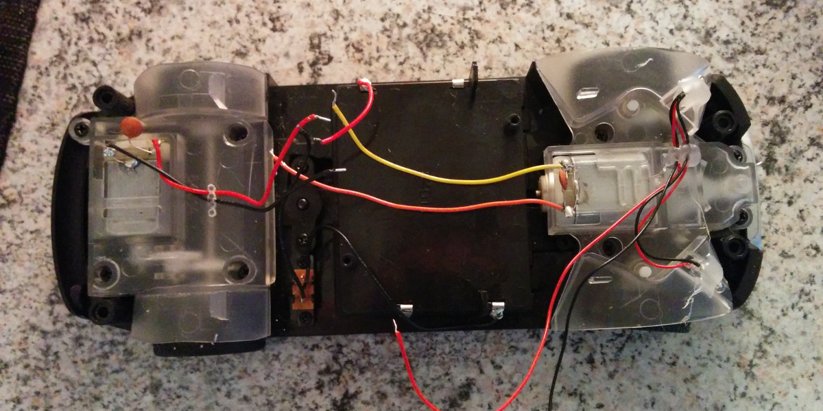
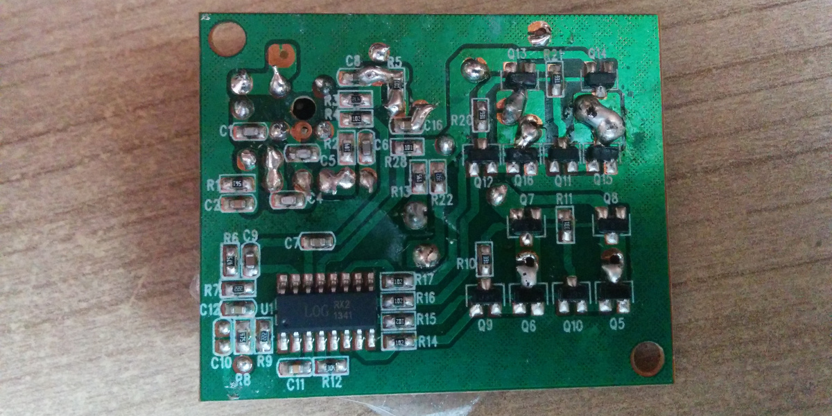
Having opened the car I found that it uses the standard RX-2/TX-2 chipset used in many cheap RC toys. Additionally the car came with two DC motors for moving and steering and LED head/taillights. After removing the original printed circuit board inside the car, there was enough room to place the ESP8266 board in it.
Controlling the motors
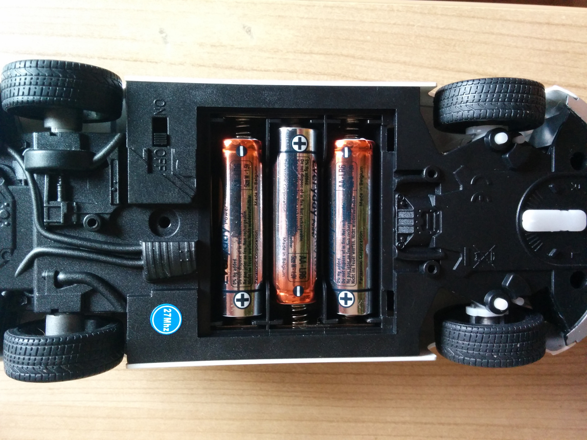
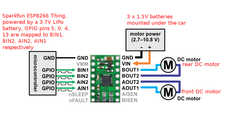
I can’t just plug the power and ground wires to my ESP8266 and hope the DC motor starts working. Firstly, the chip can output only 3.3V but the motors require higher voltage. Secondly, I need to control the rotation direction of the motors which means reversing the polarity. For power, I’m going to use the original batteries that are mounted under the car but the ESP8266 chip will be powered by the LiPo battery included with the SparkFun ESP8266 Thing. To control the motors I decided to use a Pololu DRV8833 Dual Motor Driver Carrier. It allows me to change the rotation direction and as the name implies, it can handle two motors.
Setting up the motor driver
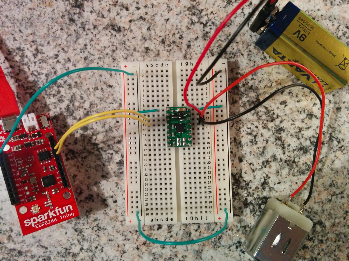
Reading the manual from Pololu helped me understand how to use the motor driver. They have great schematics and descriptions for each pin. The following is a wiring diagram provided by Pololu. Annotations in red are provided by me to describe some parts of the setup.
Before taking out my soldering iron, I tested the motor driver on a breadboard to make sure I understood everything correctly. At that point I had not yet implemented the code which would eventually control the car. To test the driver I turned the control pins on the ESP8266 board high one by one to see if the motor started rotating. When I got that working I was ready to connect the motor driver with the motors in the car.
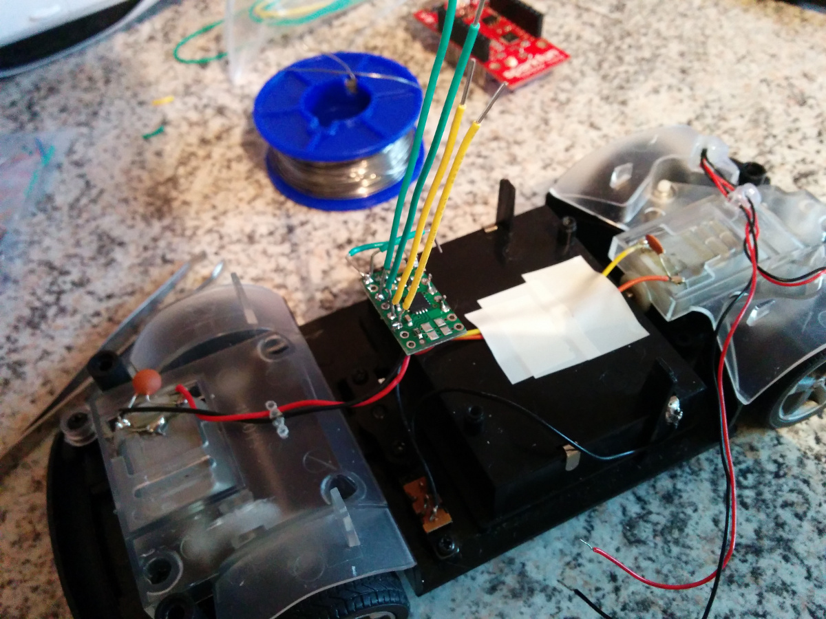
Including other components
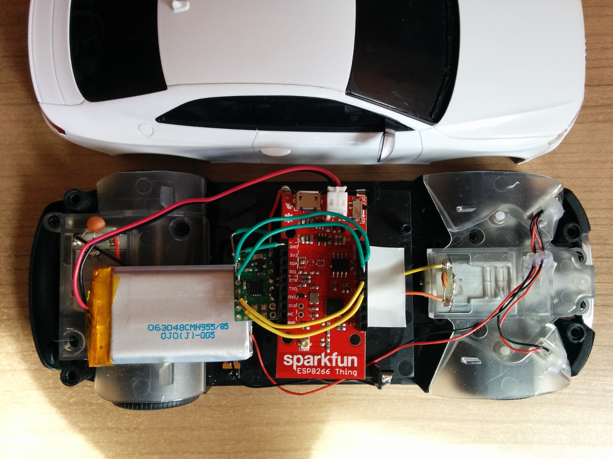
Finally, I added the ESP8266 controller to the car, connected ground and control wires with the motor driver and attached a LiPo battery. All the required components are in place. All that is left is to write the code that is going to transmit and receive commands over WiFi.
Writing control logic
Debugging the SparkFun ESP8266 Thing is not as easy as a regular Arduino board. You cannot use the serial monitor provided by the Arduino IDE. Luckily there is a simple solution for that.
I tested my initial ESP8266 code with netcat. For example, the following command sends a byte which corresponds to a turn-right command to the car. As you can see, the car has an IP address and a port it is listening on.
$ echo -e '\x03' | netcat 192.168.1.101 1111Controlling the car with netcat is not fun. Therefore the next step was to implement a small Python program which would detect keyboard presses and send commands over the network to the car. I used the old Python program I wrote for my previous project and repurposed it so it could send commands over the network instead of over a serial connection.
You can have a look at the source code of the project at Github.
TCP vs UDP
During the first tests I discovered that the car was not very responsive. The car would continue driving even when I had released all keys for example. I found that this was due to the fact that the communication was done over TCP. I’m guessing the TCP handshake process and acknowledgements introduce some overhead. After I had reengineered the car to use UDP, everything worked flawlessly.
End result
The cheap RC car (~15EUR/~17USD) which initially had only 2 channels (although the RX-2/TX-2 chipset has a third unused channel) can now be controlled programmatically. Not to mention, the ESP8266 chip supports pulse-width modulation (PWM). This means that I can control the driving speed of the car. Previously, because it had only 2 channels, it was either driving at full speed or not moving at all. Above all, since the car can be controlled over the network, I can come up with new ideas for future projects. Theoretically I could implement an app for a smartphone which would act as a custom controller.
I’m going to leave you with this video of the car in action.